Technical Articles
Technical Dry Goods | Dirkwell EX-1140 Adapter and Mitsubishi PLC CC-Link IE Field Basic Bus Communication Steps
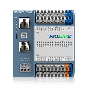
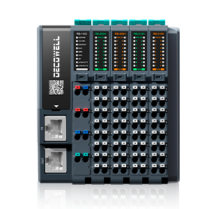
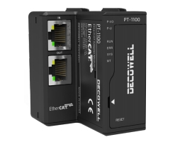
Dirkwell EX-1140 is a CC-Link IE Field Basic bus adapter. The adapter module controls fieldbus communication and realizes communication connection with the master station controller or host software.
This article will introduce how to use the Dirkwell EX card I/O module and Mitsubishi PLC configuration application operation process.
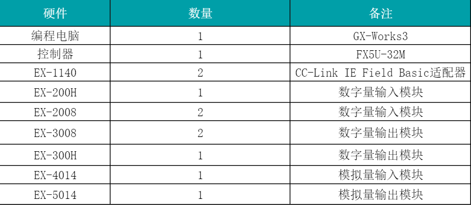
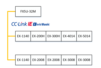
1. hardware configuration
2. communication connection diagram
3. install CSPP files
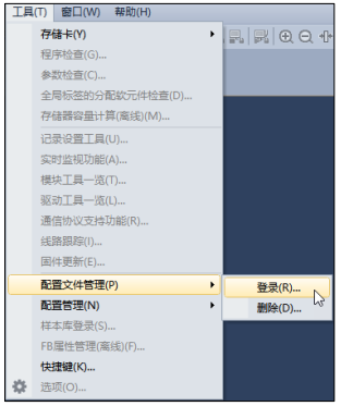
open the GX-Works3 programming software, "Tools"> "Configuration File Management"> "Login", and select the CSPP file to be installed, as shown in Figure 5-1-3.
4. Create Engineering and Configuration
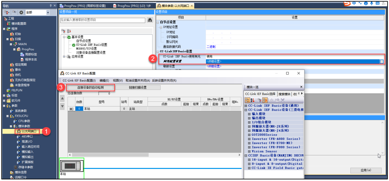
after creating a new project, select "Ethernet Port", in the module parameter window, enable the CC-Link IE Field Basic protocol, and click "Network Configuration Settings". In the CC-Link IEF Basic window, select "Automatic Detection of Connected Devices".
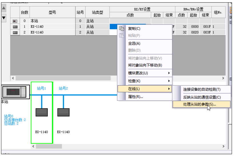
View the parameters of the slave station, right-click the first EX-1140 and select "online"> "process parameters of the slave station". in the parameter window of the slave station, select "parameter reading" and execute.
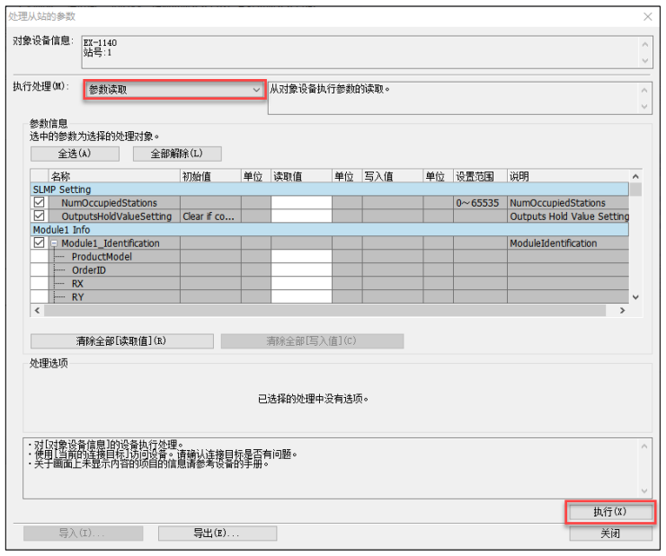
View the number of logical stations occupied by EX-1140, the model number of modules in each slot, and module address information, etc., and export this information to an Excel table.

â‘ Occupying 1 logical station
â‘¡ Slot module model and module address information
note: The address information here is offset and needs to be used in combination with the starting address set by the user.
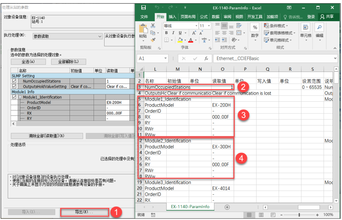
â‘ Export the read EX-1140 parameters;
â‘¡ Occupying 1 logic station;
â‘¢ Slot 1 module model and module address information;
â‘£ Slot 2 module model and module address information.
Note: The address information here is offset and needs to be used in combination with the starting address set by the user. The reaction slave station is set up and closed.
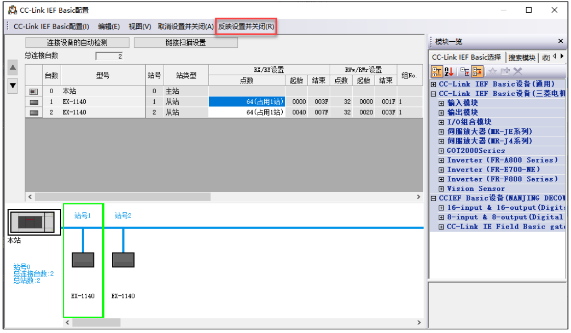
Note: The number of occupied stations uses online reading or manual calculation of the number of occupied stations. If the actual number of occupied stations does not match the set value, communication will fail.
Configure Refresh Settings
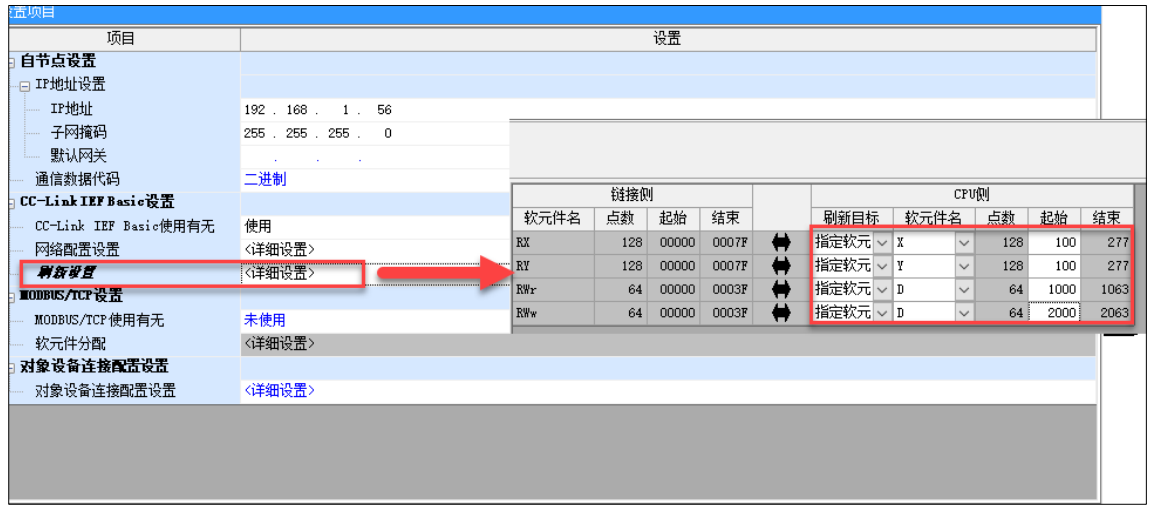
download the program to the PLC and restart the PLC with power off, forcing DO output in the monitor list.
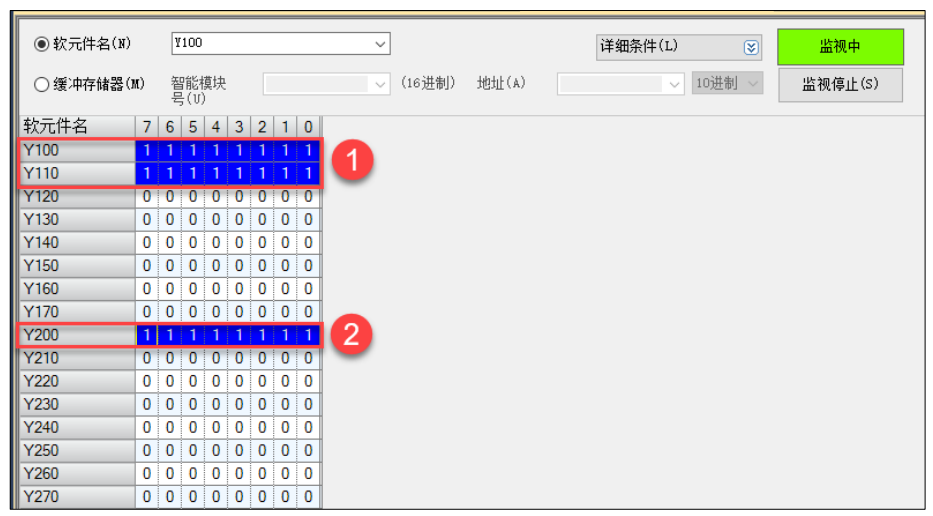
â‘ EX-300H address of slave 1 EX-1140
â‘¡ First 3008 address of slave 2 EX-1140
address corresponding to the module in the case:
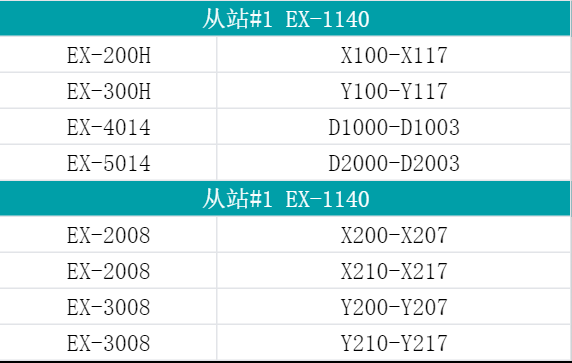
5. Configuration Bus Exception Behavior
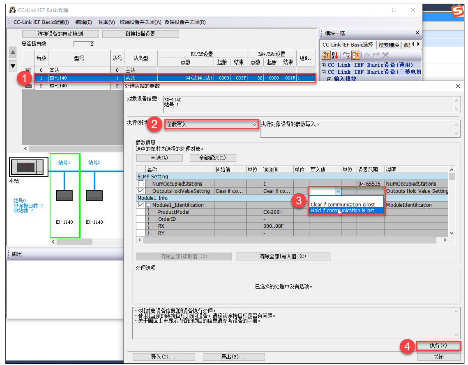
in the CC-Link IEF Basic configuration window, select the EX-1140 slave station to be configured, right-click, select "online"> "processing parameters of slave station", select "parameter write" in the parameter window of processing slave station, and modify the bus abnormal output behavior mode.
