Technical Articles
Technical Dry Goods | Operation Process of EX Card IO Module, FS Integrated Module and Mitsubishi PLC Configuration Application
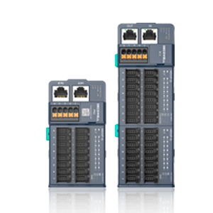
Dirkwell EX-1040 is a CC-Link bus adapter, each adapter can expand up to 32 input and output modules.
The
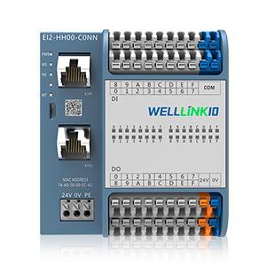
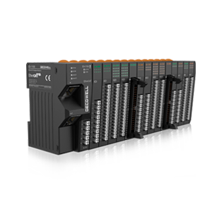
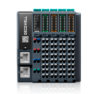
CL-HH00-C1NN is a CC-LINK bus integrated module that supports 16 digital inputs (NPN & PNP) and 16 digital outputs (PNP).
This article will introduce how to use Dirkwell EX card I/O module and FS all-in-one module and the operation process of Mitsubishi PLC configuration application.
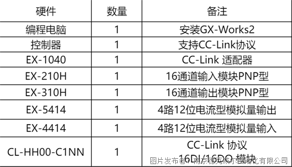
1. Hardware Configuration
2. Network Topology
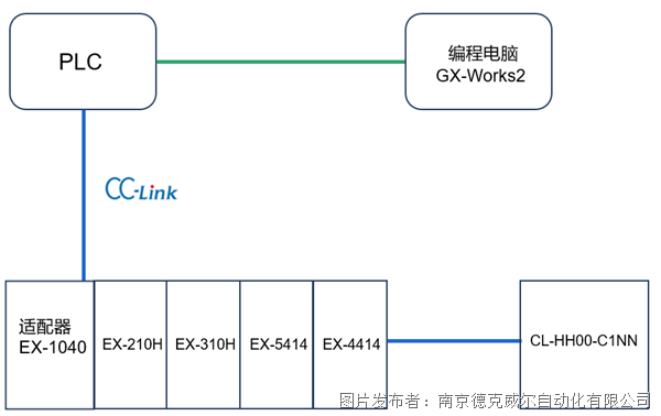
3. Device Configuration
1. new construction and communication parameter configuration
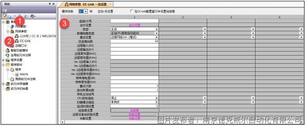
, open the GX-Works2 software, select the CPU model of the actual site, and after completion, in the navigation bar on the left side of the project, "parameters"> "network parameters"> "CC-Link", configure the CC-Link slave station setting parameters in the CC-Link parameter setting window, as shown in fig. 3, and CC-Link the network parameters, as shown in fig. 4.

2. configuration slave information
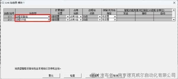
selecting "Station Information" in the CC-Link parameter setting interface, you can configure parameters such as station type, as shown in Figure 5.
the setting rules for
3. EX-1040 as a remote equipment station are as follows:
the station information of
CC-Link adapter EX-1040 in Mitsubishi GX-works software is remote equipment station, with 32 points for one station. here, it can be set according to the specific I/O points connected by the user after EX-1040. up to 4 logical stations can be set. a single logical station contains 32 points and can connect up to 4 ×(32DI 32DO 4AI 4AO).
FS series CC-Link protocol remote IO modules are used as CC-Link remote IO stations. Each module occupies 32DI and 32DO (Mitsubishi CC-Link protocol), and the module address is allocated and used.
4. considerations
1. Dialing Parameter Definition (Applicable to EX Series)
the
CC-Link remote IO adapter supports two logical station settings, determined by the first five bits and the last five bits of the baud rate dial code.
The first five bits of the
dialing code correspond to the five-layer communication rate, which is a fixed four logical stations, and the number cannot be changed by default. When the dialing code reaches the last five bits, the number of logical stations can be changed according to actual needs, and the communication rate still corresponds to the first five bit rates. The logical stations can be flexibly configured according to needs. A group of 16-point digital input and output is a logic station, and a group of 4-channel analog is a logic station.
For example, when five groups of EX-1040 are connected after PLC, one group of EX-1040 is connected with EX-210H, EX310H, EX-4414 and EX-5414, and the other two groups are configured the same. At this time, the communication rate needs to be corresponding to the main station, as shown in Table 6 for details.

2. termination resistance
add a termination resistor (110 Ω) to two terminals in the network, and the connection method of the termination resistor is shown in Figure 7 below.

